Wireless transmission of analog and binary measurement signals undoubtedly introduces a number of facilities. It will replace the cable in places where it is exposed to frequent damage, eliminates the difficulties in laying it and allows you to overcome terrain obstacles. Additionally, the devices can convert, average the signal and send the same measurement to different places. Their use introduces galvanic isolation, and the resignation from long cables will probably improve the resistance to induced disturbances.
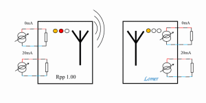
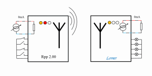
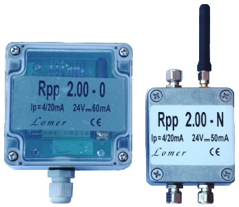
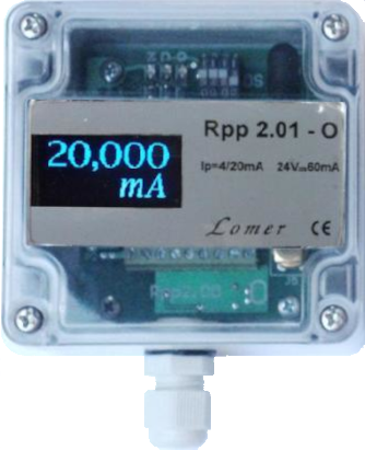
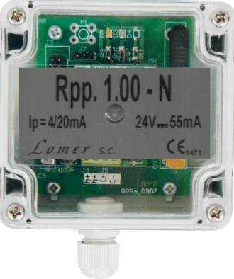
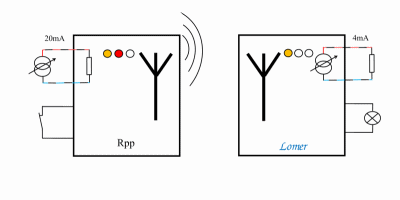
Radio, wireless transmission of analog and binary measurement signals.Advantages and application areasWireless transmission of analog measurement signals from sensors of various sizes and binary states undoubtedly has a number of advantages. It can easily turn a wired sensor into a wireless one. This allows you to speed up the installation and reduce its costs and avoid difficulties in laying the cable. Eliminates the need for jacking or interfering with the building structure. The use of wireless transmission is noteworthy when the cable is already laid, but it is frequently mechanically damaged, causing production downtime. Devices are undoubtedly indispensable for moving objects. In machine operation monitoring systems, they facilitate the reorganization of the production line, limiting the necessary work to switching on and off the appropriate transmitters without the need to change the wiring. It is also easy to put on and then dismantle temporary measurement systems in order to periodically examine the nature of a phenomenon or discover the cause of an effect. Types of transmitted signalsThe analog input and output signals can be current (0-20mA or 4-20mA current loop) or voltage (0-5V or 0-10V) type, and the ranges can be adapted to individual requirements. Binary signals can have a potential-free form (contacts of relays, limit switches, etc.) or voltage (24 V driver outputs). Similar to the analog inputs, also here you can adjust the level of the supplied voltage. The basic set of devices carries the signals in an unchanged standard, while the extended version also acts as a converter. It then changes, for example, the input voltage range of 0-5 V in the transmitter to a current range of 4-20 mA at the output of the receiver. As the transfer characteristics are established when the kit is ordered, other combinations of input and output standards are also possible. The basic design carries the 0-20 mA current loop signal without conversion. This means that the output maps to the input. To sum up, in mathematical terms, this is the characteristic y = x and therefore this version is suitable for both current ranges 0-20 mA and 4-20 mA. Number of transmitted signalsDepending on the type of devices used, two analog signals, Rpp 1.00 type, or one analog and four binary signals, Rpp 2.00 type, can be sent. A specific application is to use an analog signal as a binary using only two extreme values of current or voltage, which increases the possibility of transmitting the number of binary waveforms to five. ConfigurationEach set of devices has an individual address and works on an assigned radio channel. The simplest set, so it does not require any configuration from the user, has all the operating parameters permanently saved. In the course of production, the address and the work channel are chosen randomly. Commissioning of such a kit is limited to turning on the power after installation. Other embodiments allow the user to select the radio operating channel and the address of the set. The diversity of these two parameters enables the independent operation of the transmitter-receiver pairs in the same area (within mutual radio range). In more complex systems, groups of devices cooperating with each other are created. Way of workThe basic set consists of one transmitter and one receiver. The default mode of operation is an autonomous, unidirectional transmission of signal values with averaging in the analog path, with permanently set operating parameters. The transmitter at regular intervals samples the input signal and sends the average value at a predetermined time interval. The receiver forces the transmitted value to its output and holds it until the next reception. The work algorithm and system configuration are adjusted to the application requirements. It is possible to send the same signal to several receivers or average waveforms from different transmitters in the receiver. Rpp 2.01-O version also displays the received value and can only be used for this purpose. One binary signal can be used in the reverse configuration (input in the receiver, output in the transmitter), e.g. to control the transmission by a field controller or as a switch on the transmitting side. Due to this, the transmission on the radio channel is then bi-directional. Wireless transmission of measurement dataTechnical dataAs the descriptions of individual types of devices provide detailed lists of operating parameters, only some of them, concerning mainly the radio circuit, are presented below. They are governed by the European Telecommunications Standards Institute ETSI and are listed under ETSI EN 300-220-2 . The possible setting ranges are given in brackets and, due to interrelationships, changing one parameter it may be necessary to change another. ♦ Operating frequency: 868,29238 ( 868,0 ÷ 868,6 ) MHz
♦ Modulation type: GFSK
♦ Output power: +10 ( -10 ÷ +10 ) dBm
♦ Receiver sensitivity: -110 dBm
♦ Range: 300m w terenie otwartym
♦ Baud rate: 1,2 ( 1,2 ÷ 500 ) kbps
♦ Polite spectrum access: CCA (Clear Channel Assessment)
♦ Antenna: SMA female socket
♦ Power supply Vcc external:
- transmitter - 16 ÷ 24 V DC
- receiver - 24 V DC ±5 %
♦ Power consumption: max.- transmitter: 55 mA
- receiver: 65 mA
♦ Operating environment:
- temperature -20 ÷ +55 °C
- relative humidity < 95 %
♦ The device has a CE declaration of conformity issued on the basis of tests carried out by the Institute of Communications - PIB (notified body No. 1471)
|
Applications
|