The wireless current loop is used for radio transmission of 4-20 mA current value and forcing it on the receiving side. In addition, two binary signals are also transmitted and played back. Signals for cooperation with the field controller are also available.
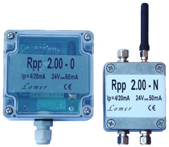
Wireless current loop 4-20 mA – Rpp 2.00
Destination
The wireless current loop is designed for radio transmission of measurement signals: one current loop 0-20 mA and two binary current ones. In addition to them, control signals are also available, described below.
The set consists of two modules: a transmitter and a receiver. The device is used in situations where the laying of the cable is associated with difficulties in the form of drilling walls, installing cable trays or digging a ditch or making a passage under a roadway or pavement.
The radio transmission takes place in the band intended for Low Power Radio Devices (LPRD), which does not require permits or fees.
Facilities
The device enables quick conversion of a sensor of any size with a current output of 0-20 mA (4-20 mA) per wireless sensor. This makes it easy to bring measurement signals to the controller. It is very useful in cases when the measuring point is moving on land, water or in the air.
An additional, beneficial effect of using the radio current loop is the galvanic separation of the measuring sensor and the object controller. This can be important in terms of measurement interference or induced destructive overvoltage, especially at long connections. It is also worth considering using the device in places where the cord is exposed to frequent mechanical damage.
The transmitter, as it can be in motion, was designed to minimize energy consumption in the sleep state. The current consumption is then 7 μA. This feature predisposes it to battery power.
Mode of action
The transmitter processes the input measuring signals and sends them to the receiver, which forces the outputs of the current and digital signals to be output. The operating status of the device is optically signaled.
The transmitter is additionally equipped with a keyed voltage output, which can be used, for example, for switching the sensor. The receiver, on the other hand, has two digital signals, input and output, designed to work with the field controller. The input can be used, for example, to control the transmission and the output to report the wireless current loop status. Giving these signals meaning depends on the needs of a particular application and takes place in the production process after consultation with the recipient.
Transmitted data packets contain an individual address, which allows the work of many devices in the same area.
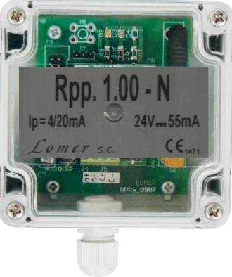
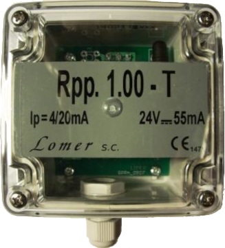
A simple version of the device is the Rpp 1.00 wireless current loop described here.
The device is delivered with fixed values of operating frequency, baud rate, output power and packet address. The above parameters can be changed at the recipient’s request in the intervals given below in brackets.
If it is necessary to display the value of the measuring current, you can use the receiver in the Rpp 2.01-O version with the OLED display. It is described here.
Wireless current loop Rpp 2.00
Technical data
The operating parameters are subject to the standards of the European Telecommunications Standards Institute ETSI and are listed in ETSI EN 300-220-2.
♦ Operating frequency: 868.29388 (868.0 ÷ 868.6) MHz
♦ Modulation type: GFSK
♦ Output power: +10 (-10 ÷ +10) dBm
♦ Receiver sensitivity: -110 dBm
♦ Range: 300m in open area
♦ Transmission: autonomous, average value every 30 s (min. 103 ms), test mode: 2 s
♦ Baud rate: 1.2 (1.2 ÷ 500) kbps
♦ Polite spectrum access: CCA (Clear Channel Assessment)
♦ Antenna: SMA female socket
 - transmitter - external
 - receiver - internal, right angle
♦ I / O signal:
 - analog: current 0-20 mA,
 - two-state:
   • transmitter: input - dry contact
   • receiver: input - LOW GND ÷ 9.0 V, HIGH 22.2 V ÷ Vcc
              output - HIGH 16.3 V at 4.75 mA
♦ Display (option): OLED, white, diagonal 1.3" (29.4 mm x 14.7 mm)
♦ Transfer accuracy: 0.25% in the 4-20 mA range
♦ AC / CA converter: 12 - bit
♦ 0-20 mA current input resistance: 100 Ω
♦ 0-20 mA output current load resistance: max. 750 Ω
♦ Power supply Vcc external:
 - transmitter - 16 ÷ 24 V DC
 - receiver - 24 V DC ±5 %
♦ Power consumption: max.- transmitter: 55 mA
                         - receiver: 65 mA
♦ Operating environment:
 - temperature -20 ÷ +55 ° C
 - relative humidity <95%
♦ Housing (W × H × D):
 - transmitter: 58 × 64 × 35, aluminum, wall mounted, IP65 (IP67 on request)
 - receiver: 82 × 80 × 55, polycarbonate, wall mounted, IP65
♦ Connections:
 - transmitter: three cable entries M8, IP68, outer diameter of the wire 3.0 ÷ 4.0 mm, core diameter max. 0.75 mm²
 - receiver: cable entry Pg7, IP68, outer diameter of the cable 3.5 ÷ 6 mm, core diameter max. 0.75 mm²
♦ The device has a CE declaration of conformity issued on the basis of tests carried out by the Institute of Communications - PIB (notified body No. 1471)
♦ At the request of the recipient, the transmitter board can be additionally protected with a protective cover.